Construction
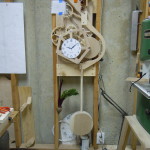
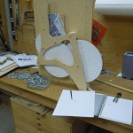
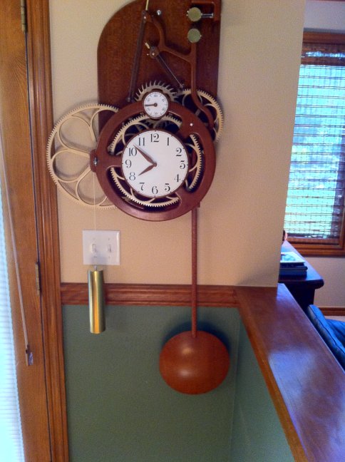
This clock was built early in 2012 and took four months–pretty much full time–to construct. The beautiful pendulum bob was made by a local turner, David Nittmann The wood is a South American lacewood, sometimes called leopardwood. The gears were cut using a jig on a table saw. All of the bearing sleeves are made of PFTE, which is a plastic with particularly low friction. The most unique aspect of the clock is the suspension. This is sometimes referred to as a “Rollamite” suspension and, as far as I know, is rarely used on clocks. The idea for this originally came from seeing it used in a seismograph. All in all, the friction in this clock rivals the best metal clocks with jeweled bearings.
Inspiration
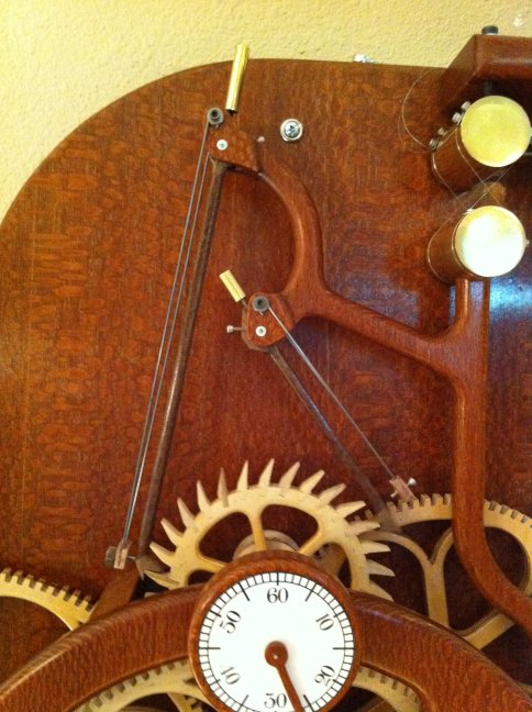
The clock uses a grasshopper escapement, which was invented around 1722 by the famous clock maker John Harrison. The original inspiration for this clock came from reading the book by Dava Sobel, The True Story of a Lone Genius Who Solved the Greatest Scientific Problem of His Time. This escapement, as far as I am aware, has never been used commercially but people who like mechanical things are usually captivated by its motion so it lives on as a result of the efforts of many clock makers.
The only other clock I have made was based on a plan for the “Swoopy” clock by Clayton Boyer. You can see that clock, and many others at Clayton’s website. In fact, several elements of the B2 design are unashamedly taken directly from the Swoopy clock–most notably the winding ratchet and motion works. (The motion works are not visible since they are pretty well hidden inside the clock face.)
Escapement
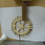
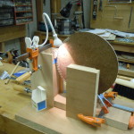
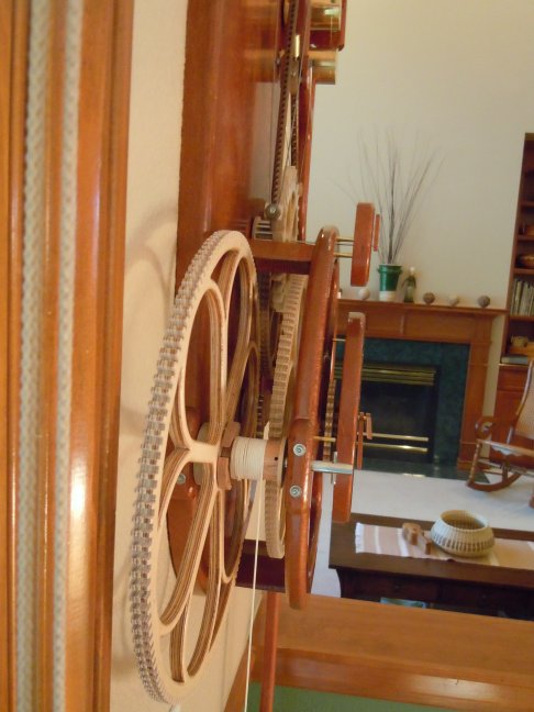
Great Wheel
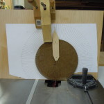
Third Wheel
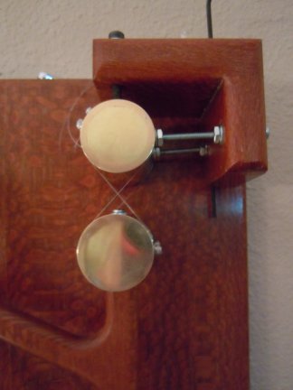
Suspension
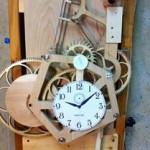
B2 clock in action
Basic mechanics of the clock
The clock is powered by a 4.5 pound weight and runs about 8 days between winds. The initial prototype of this clock had a 28-hour mechanism and ran on only a half-pound weight. By comparison the initial Swoopy clock had a 28-hour mechanism and required 9 pounds to run. This indicates that the friction of this clock has been reduced by a factor of 18 from the original Swoopy clock.
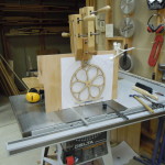
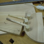
The gearing uses “lantern” gears for the pinions with a simple straight profile on the wheels. The teeth on the pinion gears are polished 1/8 inch stainless steel rods. The teeth on the wheels are cut on a table saw at about 7 degrees to engage cleanly with the pinions and to allow for some manufacturing tolerance. Other than normal woodworking tools, no special machinery was used in building the clock. I used a shop-built jig to hold the gears in place as the teeth were being cut.
The pendulum bob is directly attached to the shaft; there is no adjustment for the length of the pendulum. There is a little cup on the back of the pendulum, very near the bottom. Weights are added or removed from the cup to adjust the rate of the clock. Adding weights to the cup moves the center of oscillation downward. Adding one #8 washer to the cup causes the rate to increase by about one second per day.
Accuracy
Using the mechanism described above, the rate of the clock has been adjusted to be as close to perfect as possible. Since the clock was built, the standard deviation of the day-to-day time measurement has been a little less that two seconds per day. About a year after construction the clock would stop occasionally. I turns out that one of the screws in the escapement mechanism had come loose. Other that that, the clock has worked flawlessly.
During the initial setup and testing of the clock, I attached a photocell and microprocessor device (Arduino) to measure the period of the pendulum to an accuracy of a few microseconds. This was to aid in adjustment and to detect any potential problems in the mechanism. As expected, there was some consistent variation as each of the gears rotated. This was certainly expected because of the hand-built nature of the clock but other than some adjustment to the escape wheel, no further modifications were made to the clock.
The clock was originally designed so that profiles of the rollers in the suspension could be adjusted to make the clock isochronous. (In an isochronous clock, the period of the pendulum is constant, independent of the size of its excursion.) At the moment, I do not plan to modify the rollers since the accuracy is not likely to improve much as a result of further modification. There is probably some variation as a result of some inherent characteristics of the clock. First of all, it is a wood clock which has some natural variation due to wear and humidity. Furthermore, the clock is out in the open, mounted on an outside wall above a hot-air duct and therefore is subject to variations in drafts and temperature. All-in-all, I am pretty happy with its current operation and don’t plan any further modifications.
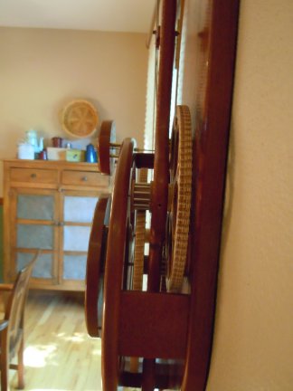
Some more pictures